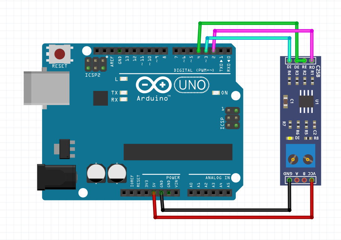
You may have noticed that DE and RE on the module are connected together. This is because one of those is set HIGH when we want to send data and the other is set LOW when we want to receive data. This combination means that while we have the flexibility to customize our interactions further, for our usage, we don't want the board to receive data at the same time we are sending data. Connecting both pins from the MAX485 allows us to use a single GPIO on the Arduino, and just toggle it's state when we send or receive.
You may have also seen MAX485 modules (or similar modules) that have flow control. To my understanding, flow control essentially tries to automate the toggle for you based on when data is being sent or not. This sounds great in theory and has been reported to work well with DMX, but some users have reported issues when trying to use flow control modules specifically with Modbus RTU.
Modbus RTU
Modbus is a fairly well-established protocol and has been around for sometime. By protocol, I mean it dictates what the data on a line looks like, how to read it and write it. Modbus does not actually care how it is transmitted, which is why you will see similar things like ModbusTCP, etc. With regard to Arduino, we usually don't have transport layer capabilities without adding a shield or ethernet module. In our case, this E3 VFD does not support ethernet (there are warnings in the manual about treating the RJ45 port as an ethernet port and the damage this would likely cause your other devices - DO NOT DO THIS).
As Modbus has been around for some time, there are already some great libraries that exist that abstract much of the heavy lifting of implementing Modbus properly. This include format, encoding, decoding, and CRC (error checking). I chose to use the library ModbusMaster. This library is simple to install and is supported by many Arduino boards right out of the gate.
Essentially, the program lets us communicate with a Modbus device using a Serial interface. It also allows us to easily setup callbacks to call before sending data and after we have sent it. This comes in really handy when we want to signal to the MAX485 transceiver module that it is time to send, otherwise it defaults to be receiving data.
I've posted some test code here.
You should be able to upload this code to your Arduino.
Testing Arduino Modbus RTU and MAX485
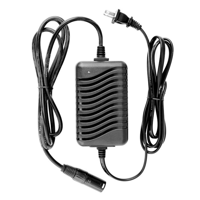
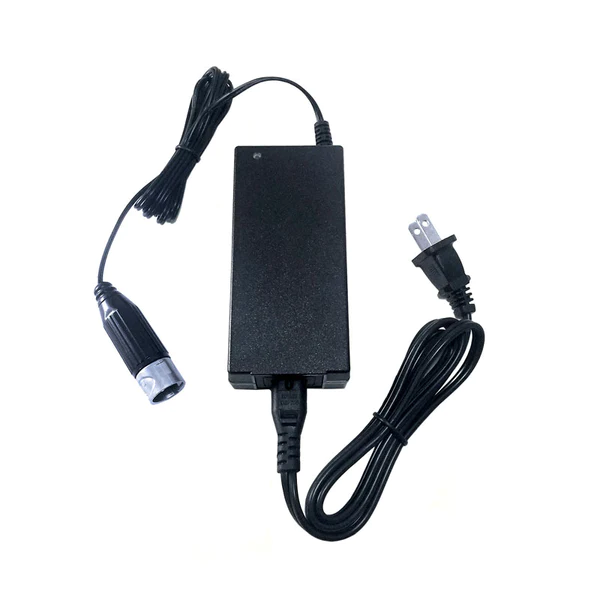
Now with our wiring of the Arduino to the MAX485 module in place, and our Arduino Uno programmed, we can now run a test. To make testing simpler, it is helpful to have another MAX485 board connected to another Arduino, or you can also buy a TTL/RS485 cable online. The prices on these cables can vary greatly, and some include more capabilities than others to support other hardware protocols.
 |
| A TTL/RS485 Cable |
For FTDI chip cables, you may need to also
install the FTDI driver like I do with DMX. With that in place, you now can connect your adapter to your computer and connect the MAX485 A to RS485A/RS485+ of the adapter and the MAX485 B to RS485B/RS485- connector. This can trip people up -- with Serial, you connect RX to TX both ways, but with RS485, you connect A to A and B to B. This is because in half-duplex communication A will always be the regular signal, and B will be the inverted signal. (If you wired them backwards on accident, it should be fine, just switch them around.) One more important thing to keep in mind is that we need to establish a common reference between the Arduino and the adapter. Connect a ground (GND) wire between them.
It all looks good, but how do we know it is working?
A great program for Windows is called Serial Debug Assistant which you can get for free from the Microsoft Store (and with awesome upgrade options). This is a serial interface program that provides many great basic options when interacting with serial communication devices. For our tests, select the COM port of the TTL/RS485 USB adapter, set the baud rate (i.e. 115200), set the data bits (for this setup it is 8), no parity bit, and 1 stop bit. Now click Open Serial Port. If the software was able to connect successfully, you should see the button change to say Close Serial Port. I also like to set the Receive settings in Serial Debug Assistant so that the HEX display is on and Auto break frame is set to 20ms. For Send settings, check the HEX send box to send responses (more later).
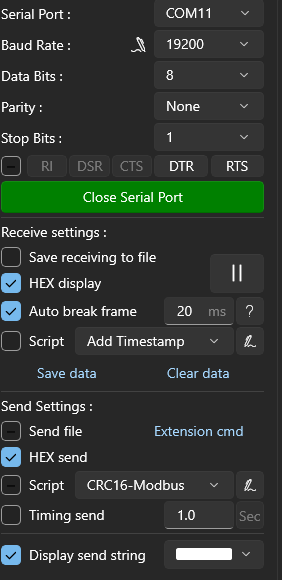 |
| My Settings in Serial Debug Assistant |
A note about communication using Modbus. Often, we setup these configurations with one main controller or master (the devices asking for data from others) with one or more peripheral or slave devices (the devices returning data). The connected slave devices will only respond when asked to update something or return a value, otherwise they are quiet. Also, there is only ever 1 master. In our Arduino setup, the Arduino is the master device. For testing with the PC, the PC is a slave device. That means that the PC should only respond when requested from the Arduino.
With a connection between Arduino and the PC setup correctly, and Serial Debug Assistant successfully connected to our USB TTL/RS485 adapter via a com port, we should now be able to see the data coming from the Arduino. It may look like this if you left the Arduino code as it was:
01 03 00 06 00 01 64 0B
Which breaks down like this:
These are created from https://npulse.net/en/online-modbus which has some great tools to help with this process. If you wish to return a response from Serial Debug Assistant, you can enter this and hit send:
01 03 02 00 34 B9 93
This response just returns some random data (in this case the decimal value 34).
Later, we will add a lot more meaning with how we handle use this. For now, however, we just want to make sure we have data correctly moving into and out of the Arduino.
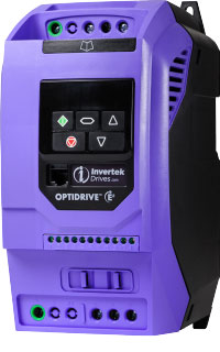
Invertek Optidrive E3
As I have mentioned before, the RJ45 port on the front of this particular VFD is NOT an ethernet port. This port, though, gives us access to the A/B lines for RS485. I made part of an ethernet cable and left the wires on the other end exposed. I decided to align the ethernet cable according to T-568B wiring spec, but for this it doesn't really matter, just make sure your using the correct wires positions as they are described in the manual. For this project, I clipped everything that wasn't wire 3 (GND), or wires 7/8 (A/B lines). I have no desire to accidentally connect something with 24v :).
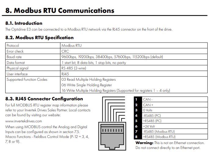 |
| Page 36 snippet from the Invertek Optidrive E3 Manual |
The manual also will tell us how to setup the configuration for our VFD. Specifically, we need to make sure the values are setup correctly for P-36 (parameter 36). You can hold down the top center button on the VFD to enter into a settings mode, then using the arrow buttons, navigate to P-36, how click the same center button as before, it should change to show Adr 1. Clicking the same center button will let you cycle through all the settings for this parameter group. Make sure these settings match the ones from before (i.e. Baud 115200 [shown as 115.2]). The manual describes the other settings needed for this connection.
Now let's remove the MAX485 and Arduino connection from our USB TTL/RS485 adapter and instead connect our ethernet wires up. Although slightly confusing, when the manual says RS485+, this is the same as A, and RS485- is the same as B.
With everything connected properly (and double-checked), let's turn on the VFD and plug in the USB TTL/RS385 adapter. Open Serial Debug Assistant and make sure to connect to the adapter again with the same settings as before.
Now in this configuration, the master device is going to be the PC and the slave device is the VFD. So we need to be first to send data to the VFD to have it respond. Let's send a request to see what the temperature of the VFD is. In the input area, enter:
01 03 00 39 00 01 04 0D
Now hit enter. If everything is working as it should, you should immediately get back a response like the one we sent out before. The data portion of the message should represent the temperature of the VFD.
Connecting Everything Together
As you probably have guessed by now, we are going to connect the MAX485/Arduino directly to the VFD. The USB TTL/RS485 adapter won't do us much good here (unless you want to man-in-the-middle like I did), but by using the Arduino serial monitor, we can query any of the read registers on the VFD. We can also set new values for write registers.
You should now have a working connection and communication between Arduino and the VFD.
Hopefully you found this helpful, but feel free to ask questions. Fair warning, I do not know anything about other VFDs and would do exactly what you would (look in the manual) to try and figure it out. If you want to hire me to read your VFD manual, I suppose you could :). If there is no manual, I'm not aware of any easy shortcuts to figure out the connections. My advise would likely be to start with a multimeter and try to find voltage and ground, then operate the VFD and take measurements, maybe use an oscilloscope, and see what you can deduce. Although, it would probably be cheaper considering time/cost to just buy a VFD that you know has support for Modbus and has a good manual.
Support the Developers
If you find the free software referenced above useful, make sure you try to find ways to support those developers as that will go a long way to making sure these tools stay awesome for everyone.
Getting a TimedOut error in ModbusMaster (226)?
At first, I tried to connect everything with the baud rate 19200, and everything was working fine except that the responses back to Arduino would timeout every time. It turns out that there is a set amount of time to get a response, and if it doesn't happen quick enough, the library will timeout. You can modify the code, or in my case, I just increased the baud rate to 115200 which happens to be the default value for the VFD anyway. This change has been working well.
Flaky data transmissions? Random transmission failures?
My first attempt at this used SoftwareSerial to replicate a hardware serial with hopes that I could use an Arduino that did not have Serial1 or so on. After hooking my USB TTL/RS485 adapter into the communication between Arduino and the VFD, I found that all the values being exchanged were actually correct, but my Arduino program would randomly report bad CRC, TimedOut, or other errors. As I had already had a bit of trouble with the TimedOut error before due to timing, I determined this is likely also an issue with timing, but one I'm not sure I can code to fix. Instead of messing with all that, however, I decided to change my Arduino UNO R3 board for an Arduino Mega2560. The mega is a more capable board and possibly overkill for what I'm doing, but I had it on hand and I knew it has additional dedicated hardware Serial. After a quick update to my code (trading out SoftwareSerial for Serial1), and a switch over on wiring to use RX1/TX1 GPIO on the mega, I was up and running. The flaky communication issues from before have been resolved.
VFD Doesn't Start / Register Values Don't Return Correctly
One thing to note is that ModbusMaster uses a zero-based addressing system for registers, but the E3 uses a 1-based addressing for registers. This means you need to subtract 1 from the register listed in the documentation to properly.
In the E3 documentation, it states:
NOTE For Master devices which use zero based addressing and therefore treat the first Register address as Register 0, it may be
necessary to convert the Register Numbers detailed below by subtracting 1 to obtain the correct Register address.
Another possible reason would be that the VFD does not have a required connection between terminals to allow for remote control. In our setup, we use an emergency stop button that is NC to solve this. It is between terminal numbers 1 & 2.
Example Code:
https://gist.github.com/mcorrigan/8d1016a028e831d788095c0bebc5d89b
Resources and Links:
https://goemc.com/ (Our VFD Supplier)
https://npulse.net/en/online-modbus (Modbus protocol tools online)
https://www.circuitstate.com/tutorials/what-is-rs-485-how-to-use-max485-with-arduino-for-reliable-long-distance-serial-communication/ (comprehesive look at RS485 and MAX485)
https://github.com/4-20ma/ModbusMaster (Arduino Library for MAX485)
https://www.microsoft.com/store/productId/9NBLGGH43HDM?ocid=pdpshare (Serial Debug Assistant)
https://inverterdrive.com/file/Invertek-Optidrive-E3-Manual (VFD Manual)
https://www.wolfautomation.com/media/pdf/ac-drives/invertek/ode/invertek-e3-an-ode-3-038-21.pdf (VFD Manual - Additional details, like corrected Modbus register map)
https://github.com/4-20ma/ModbusMaster/issues/127 (ModbusMaster timeout error)
https://www.youtube.com/watch?v=owxWr8vdzSM (An example of sending data to the VFD)


